
Chirps to Bytes: Decoding LoRa with a Low-Cost Software-Defined Radio
Exploring the physical layer of digital radio using inexpensive hardware and open-source signal-processing tools.
A commercial radio transceiver typically handles modulation, synchronisation and decoding internally, presenting the application with a stream of transmitted or received data. This is convenient for system integration, but less useful when the objective is to understand how the physical layer behaves and what determines whether a signal can be recovered.
Software-defined radio (SDR) provides an alternative. By capturing the received waveform as raw in-phase and quadrature (I/Q) samples, we can examine the signal and process it in software, with access to the individual stages of reception.
I recently explored this using LoRa, a low-power digital radio technology based on chirp spread spectrum modulation. With a commercial LoRa development board, an inexpensive RTL-SDR receiver and open-source software, I was able to capture and decode transmitted packets. The immediate objective was relatively modest: establish a working transmit-and-receive chain and understand its operation. The more interesting prospect is using that setup to investigate receiver performance, synchronisation and the effects of channel impairments.
Why LoRa?
LoRa (Long Range) is a proprietary physical-layer modulation technology owned by Semtech. It is widely used in low-power wireless systems where range and energy consumption are more important than high data rates. It is distinct from LoRaWAN, the higher-level networking protocol that adds functionality including network management, authentication and encryption.
LoRa is an interesting subject for SDR experimentation because its modulation is relatively straightforward to understand, while its practical receiver incorporates many of the signal-processing challenges encountered in more complex digital communication systems.
At the heart of LoRa is chirp spread spectrum (CSS). Rather than representing data through conventional fixed-frequency carrier states, LoRa uses signals whose instantaneous frequency sweeps across the channel bandwidth. Each symbol is represented by a cyclically shifted up-chirp: a rising-frequency sweep that wraps around when it reaches the upper edge of the channel. The amount of shift encodes the transmitted symbol value.
Three parameters govern much of the resulting behaviour: spreading factor , bandwidth and coding rate. Spreading factor is the number of bits carried by each symbol, so a symbol can take one of values. The SX1262 radio used here supports SF5 to SF12. Bandwidth is the width of the frequency range each chirp sweeps across, measured in hertz. Coding rate is the proportion of transmitted bits that carry data, from 4/5 to 4/8; the remainder is redundancy for forward error correction. More redundancy makes a packet take longer to send but lets the receiver recover from more errors: at 4/7 and 4/8 it can correct a single bit error in each block of four data bits.
The relationship between spreading factor and the time taken to send one symbol - symbol duration, - is particularly important:
At SF9 and a bandwidth of 125 kHz, a symbol lasts 4.096 milliseconds. Increasing the spreading factor to SF12 extends that duration to 32.768 milliseconds. The longer symbol duration generally improves receiver sensitivity under suitable conditions, but substantially increases packet airtime and reduces throughput.
These trade-offs are central to LoRa’s usefulness. Its physical-layer parameters allow a system designer to favour range and sensitivity or higher data rates, subject to practical constraints such as channel conditions, spectrum occupancy and permitted transmission duty cycle.
How the receiver recovers a symbol
The principle behind LoRa demodulation is an elegant application of frequency-domain signal processing.
The receiver first has to identify the incoming transmission and align itself with the symbol boundaries. Once synchronised, it multiplies each received up-chirp by a locally generated reference down-chirp. Because the two chirps sweep in opposite directions, their frequency changes cancel. The result is a tone whose frequency is constant apart from a jump of exactly one bandwidth at the point where the transmitted chirp wraps around. When the signal is sampled at a rate equal to the bandwidth, that jump aliases onto the same frequency, leaving a single steady tone.
The frequency of this tone identifies the original symbol. A Fast Fourier Transform (FFT) converts the resulting signal into the frequency domain, where the strongest bin indicates the transmitted value.
For example, SF9 gives 512 possible symbol values. In an ideal, correctly synchronised receiver sampling at the channel bandwidth, a 512-bin FFT can distinguish the corresponding tones after dechirping. A transmitted symbol with value 256 produces a peak at the associated frequency bin.
This makes the underlying modulation relatively accessible: a changing-frequency signal is converted into a steady tone, and the tone’s frequency reveals the data.
Real-world reception is less straightforward. The transmitter and receiver have independent oscillators, so their carrier frequencies will not be perfectly aligned. The receiver also has to determine precisely when each symbol begins. Either error can shift or spread energy between FFT bins, leading to incorrect symbol decisions. The two errors are also hard to tell apart. In a chirp, frequency is tied to time, so a timing error and a frequency offset both appear as a shift of the FFT peak, and from up-chirps alone the receiver can measure only their sum. The LoRa preamble therefore ends with down-chirps, on which a timing error moves the peak in the opposite direction while a frequency offset does not. Comparing the two measurements lets the receiver separate the errors.
A practical LoRa receiver therefore needs more than a dechirping operation. It must detect the packet preamble, estimate timing and frequency errors, correct them sufficiently for demodulation, and then recover the encoded data. Forward error correction provides an additional means of recovering information when some of the symbol decisions are incorrect.
These are precisely the stages that make a software-defined implementation useful for experimentation.
Building and testing the receiver
For the transmitter, I used a Heltec WiFi LoRa 32 (V4) development board incorporating a Semtech SX1262 radio. The board ran a simple Arduino sketch that periodically transmitted a short text message with an incrementing packet identifier.
The receiver was a Nooelec RTL-SDR USB device, which is considerably less expensive than a dedicated laboratory SDR. Although its limitations are well known, it provides sufficient functionality to capture LoRa transmissions for offline processing.
The experiment operated at 869.525 MHz, within the UK’s 869.4–869.65 MHz short-range device band. I configured the transmitter for SF9, 125 kHz bandwidth, coding rate 4/7, an eight-symbol preamble, an explicit header and payload CRC checking, and left the sync word at the driver’s private-network default of 0x12. The configured transmit power was 10 dBm. With a payload of seven or eight bytes, each packet occupied approximately 140 milliseconds of airtime.
Transmissions were separated by approximately five seconds, comfortably within the relevant band’s 10% duty-cycle limit. Operation in this licence-exempt band remains subject to the applicable power and other regulatory requirements.
On the receive side, I used rtl_sdr to record raw I/Q samples at 1 MS/s. The SDR was tuned 225 kHz below the nominal transmit frequency to avoid placing the signal at the receiver’s DC-centre artefact. SDR++ provided a visual check of the received spectrum before I attempted to decode the recording.
For the decoder, I used GNU Radio and gr-lora_sdr, the open-source LoRa physical-layer implementation developed at EPFL. A Python script, lora_rx_rtl.py, arranged the processing of the captured samples using the GNU Radio receiver components.
The advantage of this approach was that I did not need to implement an entire LoRa decoder before examining real signals. The existing implementation provided a functioning reference receiver, while preserving access to the signal-processing stages and their configuration.
Starting with the recorded samples, the script first undid the deliberate tuning offset: a frequency-translating filter shifted the LoRa channel back to 0 Hz and low-pass filtered it to remove energy outside the channel. The receiver then searched for a LoRa preamble, established symbol timing and compensated for the residual frequency offset between the two oscillators. The synchronised signal was dechirped and transformed into the frequency domain. Rather than simply picking the strongest bin, the receiver was configured for soft-decision decoding, passing a likelihood for each bit to the later stages.
Recovering the original message required further processing. The demodulator output passed through the remaining gr-lora_sdr stages in turn: Gray mapping, deinterleaving, Hamming decoding and dewhitening. The receiver also decoded the packet header and checked the payload CRC before presenting the recovered data.
The complete process takes us from a recording containing nothing more than complex samples of the received waveform to the original transmitted text.
With the transmitter and receiver configured consistently, the decoder recovered multiple packets with the expected messages and sequential identifiers, each passing its header checksum and payload CRC (Figure 1). The SDR++ display shows the transmissions occupying about 869.46–869.59 MHz, the expected 125 kHz around 869.525 MHz (Figure 2).
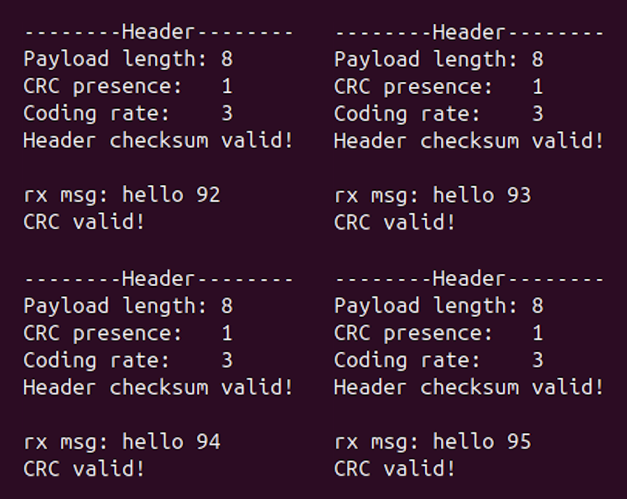
Figure 1. Decoder output for four consecutive packets (hello 92–95), each passing the header checksum and payload CRC.
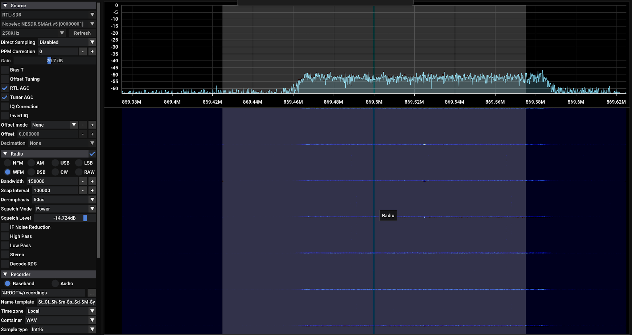
Figure 2. SDR++ spectrum and waterfall around 869.5 MHz. Each horizontal line in the waterfall is one LoRa transmission, spanning about 869.46–869.59 MHz. The shaded band and red line mark the SDR++ tuning window.
This established that the end-to-end chain was working: a commercial LoRa transmitter generated packets, an inexpensive SDR captured their waveforms, and an open-source software receiver recovered the transmitted information.
It did not yet establish the sensitivity or reliability of the receiver under adverse conditions. For that, we need controlled measurements rather than a successful demonstration.
From successful reception to measured performance
Having established a working receiver, I can now begin investigating the factors that determine whether packets are recovered successfully.
One useful starting point is the relationship between signal-to-noise ratio (SNR) and packet-error rate. By taking a known I/Q recording and introducing calibrated levels of noise, it should be possible to measure how the probability of successful packet recovery changes as signal quality deteriorates.
Repeating the experiment with different spreading factors and coding rates would make the trade-offs between airtime, throughput and error tolerance measurable rather than simply relying on published specifications.
There are other questions worth investigating. For example, how much carrier-frequency offset can the receiver tolerate before acquisition or demodulation fails? How much mismatch between the transmitter and receiver clocks can it absorb before symbol timing drifts too far within a packet? What happens when narrowband interference is introduced into part of the chirp bandwidth, or when a second signal occupies the same channel?
The answers will not necessarily be captured by a single packet-error-rate figure. A receiver can fail because it never detects the packet, because it cannot establish synchronisation, or because errors remain after demodulation and decoding. Access to the processing chain allows these failure modes to be distinguished.
This is a significant advantage of the SDR approach. Rather than treating packet reception as a binary result reported by a transceiver, we can inspect the signal and investigate which mechanisms are responsible for success or failure.
Resilience does not imply low observability
LoRa is sometimes discussed in connection with resilient or low-observable communications because chirp spread spectrum can support reception at low SNR. These characteristics are interesting, but they should not be taken as evidence of capabilities that have not been measured.
A receiver’s ability to recover information from a weak signal is one aspect of communications resilience. Resistance to deliberate interference is another, and the two are not interchangeable. Performance against a jammer depends on the form of interference, its power relative to the wanted signal, and the receiver’s acquisition and demodulation behaviour.
Low probability of detection (LPD) and low probability of interception (LPI) introduce further questions. A transmission that can be decoded at low SNR is not necessarily difficult for another receiver to detect or classify. Conventional LoRa packets have recognisable preambles and a well-characterised chirp structure, both of which can be exploited by a receiver designed to identify them. Transmission timing, bandwidth and repetition patterns can provide additional information to an observer.
Whether a signal is difficult to detect or intercept depends on the capabilities of the observer, the signal environment and the characteristics of the transmission. It cannot be inferred from the modulation’s nominal processing gain or receiver sensitivity alone.
Nor does LoRa’s physical layer inherently provide confidentiality or authentication. The 0x12 sync word used in my experiment identifies a packet or network configuration; it is not a cryptographic security mechanism. Similarly, a valid CRC confirms that a packet has passed an error-detection check, but does not establish who transmitted it or protect against deliberate manipulation.
LoRaWAN provides security functions at higher protocol layers, but these are separate from the LoRa modulation used here.
For communications engineering, it is useful to distinguish reliable reception, resistance to interference, detectability and information security. Each requires its own threat assumptions, experimental methods and supporting evidence.
LoRa provides a practical platform for examining some of these questions, but the initial experiment demonstrates only that packets can be captured and recovered under the conditions tested.
Next steps
With packet capture and decoding working, the next step is to investigate how receiver performance changes with different LoRa configurations and controlled channel impairments. The combination of inexpensive hardware and open-source SDR tools makes it possible to move quickly between experiments, with direct access to signals and processing stages that would otherwise remain inside the transceiver.
The same approach can be applied, where transmissions are permitted or signals are generated without radiating, to other modulation and spread-spectrum techniques, including direct-sequence spread spectrum, frequency hopping and OFDM. Each presents different synchronisation challenges, receiver architectures and trade-offs in spectral efficiency and interference tolerance.
For now, the LoRa experiment provides a working starting point. I can use it to examine how receiver behaviour changes as conditions deteriorate, identify where processing fails and evaluate potential improvements without rebuilding the transmit-and-receive chain for each investigation.
References and further reading
- Semtech, LoRa Modulation Basics, AN1200.22. Background on LoRa’s chirp spread spectrum modulation and physical-layer characteristics.
- Tapparel et al., gr-lora_sdr. Open-source GNU Radio implementation of the LoRa physical layer.
- Ofcom, UK Interface Requirement IR 2030. UK spectrum requirements for short-range devices.